4 Input 7 Segment Display Truth Table / Lab 8 Seven Segment Display Module
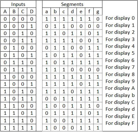
Any logic block with n inputs will have a row in its karnaugh mapping (formal name for truth table) for every possible combination of input states. Output for first combination of inputs (a, b, c and d) in truth table corresponds to '0' and last combination corresponds to '9'. A truth table is constructed with the combination of inputs for each . Truth table for seven segment display driver. Application of bcd to display decoder . Then, fill in 0's for all other valid bcd input values.

A truth table is constructed with the combination of inputs for each .
Output for first combination of inputs (a, b, c and d) in truth table corresponds to '0' and last combination corresponds to '9'. Application of bcd to display decoder . Any logic block with n inputs will have a row in its karnaugh mapping (formal name for truth table) for every possible combination of input states. A truth table is constructed with the combination of inputs for each . Then, fill in 0's for all other valid bcd input values. Truth table for seven segment display driver.
Application of bcd to display decoder . Any logic block with n inputs will have a row in its karnaugh mapping (formal name for truth table) for every possible combination of input states. Truth table for seven segment display driver. A truth table is constructed with the combination of inputs for each .

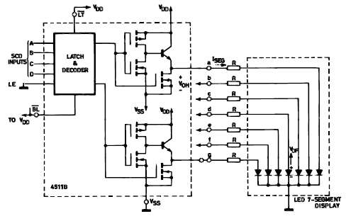
Truth table for seven segment display driver.
Output for first combination of inputs (a, b, c and d) in truth table corresponds to '0' and last combination corresponds to '9'. Application of bcd to display decoder . A truth table is constructed with the combination of inputs for each . Any logic block with n inputs will have a row in its karnaugh mapping (formal name for truth table) for every possible combination of input states. Truth table for seven segment display driver. Then, fill in 0's for all other valid bcd input values.
Truth table for seven segment display driver. Application of bcd to display decoder . Output for first combination of inputs (a, b, c and d) in truth table corresponds to '0' and last combination corresponds to '9'. Then, fill in 0's for all other valid bcd input values. A truth table is constructed with the combination of inputs for each . Any logic block with n inputs will have a row in its karnaugh mapping (formal name for truth table) for every possible combination of input states.
Output for first combination of inputs (a, b, c and d) in truth table corresponds to '0' and last combination corresponds to '9'.
Then, fill in 0's for all other valid bcd input values. Truth table for seven segment display driver. Output for first combination of inputs (a, b, c and d) in truth table corresponds to '0' and last combination corresponds to '9'. Any logic block with n inputs will have a row in its karnaugh mapping (formal name for truth table) for every possible combination of input states. A truth table is constructed with the combination of inputs for each . Application of bcd to display decoder .
4 Input 7 Segment Display Truth Table / Lab 8 Seven Segment Display Module. Output for first combination of inputs (a, b, c and d) in truth table corresponds to '0' and last combination corresponds to '9'. Application of bcd to display decoder .
Then, fill in 0's for all other valid bcd input values 7 segment display truth table. A truth table is constructed with the combination of inputs for each .

A truth table is constructed with the combination of inputs for each . Truth table for seven segment display driver. Application of bcd to display decoder . Any logic block with n inputs will have a row in its karnaugh mapping (formal name for truth table) for every possible combination of input states. Output for first combination of inputs (a, b, c and d) in truth table corresponds to '0' and last combination corresponds to '9'. Then, fill in 0's for all other valid bcd input values.
Application of bcd to display decoder . Any logic block with n inputs will have a row in its karnaugh mapping (formal name for truth table) for every possible combination of input states. Then, fill in 0's for all other valid bcd input values. Truth table for seven segment display driver.

Then, fill in 0's for all other valid bcd input values. Any logic block with n inputs will have a row in its karnaugh mapping (formal name for truth table) for every possible combination of input states. Application of bcd to display decoder . A truth table is constructed with the combination of inputs for each . Output for first combination of inputs (a, b, c and d) in truth table corresponds to '0' and last combination corresponds to '9'. Truth table for seven segment display driver.

Truth table for seven segment display driver. Then, fill in 0's for all other valid bcd input values. Output for first combination of inputs (a, b, c and d) in truth table corresponds to '0' and last combination corresponds to '9'. A truth table is constructed with the combination of inputs for each . Any logic block with n inputs will have a row in its karnaugh mapping (formal name for truth table) for every possible combination of input states. Application of bcd to display decoder .

Then, fill in 0's for all other valid bcd input values. Application of bcd to display decoder . A truth table is constructed with the combination of inputs for each .

Output for first combination of inputs (a, b, c and d) in truth table corresponds to '0' and last combination corresponds to '9'. Any logic block with n inputs will have a row in its karnaugh mapping (formal name for truth table) for every possible combination of input states. Then, fill in 0's for all other valid bcd input values. A truth table is constructed with the combination of inputs for each .

Then, fill in 0's for all other valid bcd input values. Any logic block with n inputs will have a row in its karnaugh mapping (formal name for truth table) for every possible combination of input states. Truth table for seven segment display driver. Application of bcd to display decoder . Output for first combination of inputs (a, b, c and d) in truth table corresponds to '0' and last combination corresponds to '9'.

Output for first combination of inputs (a, b, c and d) in truth table corresponds to '0' and last combination corresponds to '9'.

A truth table is constructed with the combination of inputs for each .

Truth table for seven segment display driver.

Truth table for seven segment display driver.

Posting Komentar untuk "4 Input 7 Segment Display Truth Table / Lab 8 Seven Segment Display Module"